Introduction
Bearings support the load of various components while ensuring no metal-to-metal contact occurs between them. In this article, we take a look at how to measure the various bearing clearances in the main engine of a ship.
Main Engine Clearances
In the main engine, we must measure clearances of the main bearings, crank pin bearings, and crosshead bearings from time to time. The recommended interval between clearances can be found in the manual.
The clearance values must then be compared to the allowable values in the machinery manual to understand the extent of wear. A higher clearance denotes excessive wear which may necessitate the renewal of the bearing when beyond allowable limits.
The intention behind measuring clearances is to keep a check on the bearing thickness. By measuring say, every 1000 hours, we can understand the rate of wear of bearings by comparing it to the previous reading.
Let us start with the procedure to measure the main bearing clearance in the main engine:
Main Bearing Clearance Measurement
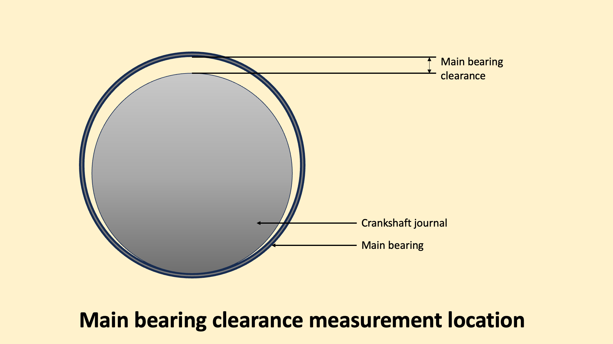
The main bearing clearance is the distance between the crankshaft journal and the bearing’s inner surface. Due to the heavy weight of the crankshaft, when the engine is stopped, it rests on the bearing shell at the bottom. The clearance for the main bearing is therefore measured at the top.
There are several ways to measure the main bearing clearance. Let’s take a look at two of the most common ones. These are:
-
Using a telescopic feeler gauge
-
Using a dial gauge through the LO pipe assembly holes.
Using a telescopic feeler gauge
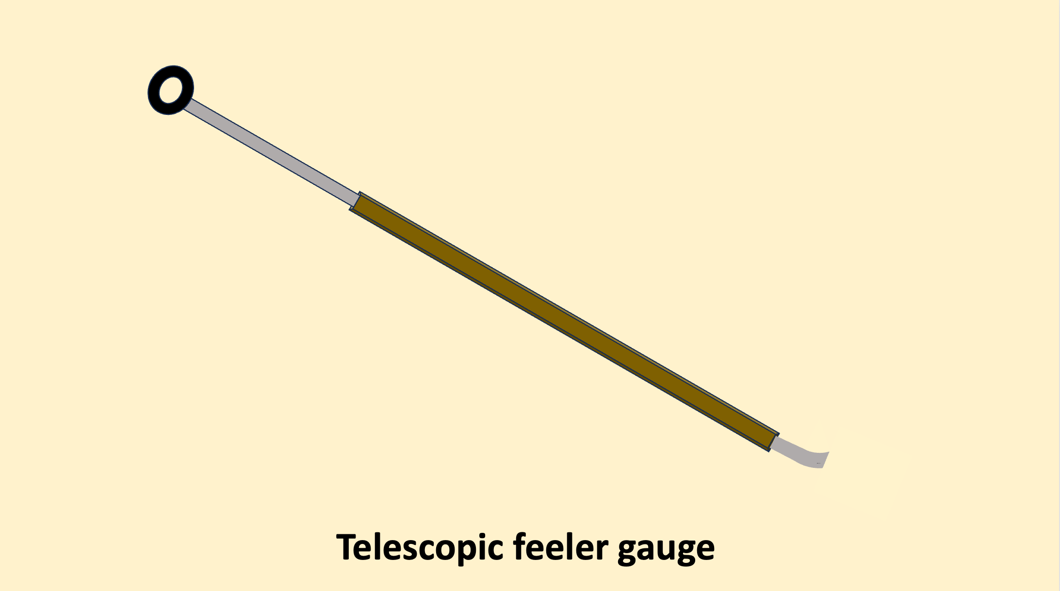
As mentioned earlier, the position of the piston has no effect on the main bearing clearance measurement. But when measuring with a telescopic feeler gauge, we keep the crank throw flat so that we can use it as a support to conduct the measurements.
Once in position, the telescopic gauge is inserted along the surface of the crankweb to the position where it meets with the crankshaft journal.

The gauge must not be forced into the clearance. This may cause the gauge to break and get lodged into the clearance. The biggest size that goes in easily is the ME bearing clearance. By measuring the current clearance with the last measured clearance, we can calculate the wear rate.
What can be done if the feeler gauge breaks inside the main bearing clearance?
A feeler gauge plate breaking inside the main bearing is a very serious problem. It cannot be left inside the bearing under any circumstances and must be removed before we can start the engine. There are two simple methods to remove a broken feeler gauge.
The first method is to put two equal sized feeler gauges on each side of the broken feeler gauge and pull it out. The second method is to run the LO pump. The pressure from the LO may remove the broken piece from the clearance cavity.
If both of these methods do not work, we have to open the bearing housing and remove the piece. The incident may also call for a bearing replacement.
Using a dial gauge through the LO pipe assembly holes
A second method to measure the bearing clearance is to use a dial gauge. The dial gauge is first calibrated in a calibrator and set to zero.
We then open the LO pipe assembly on top of the main bearing housing and insert the dial gauge into the designated hole.

The typical value of main bearing clearance is around 0.4 mm.
Crankpin Bearing Clearance Measurement
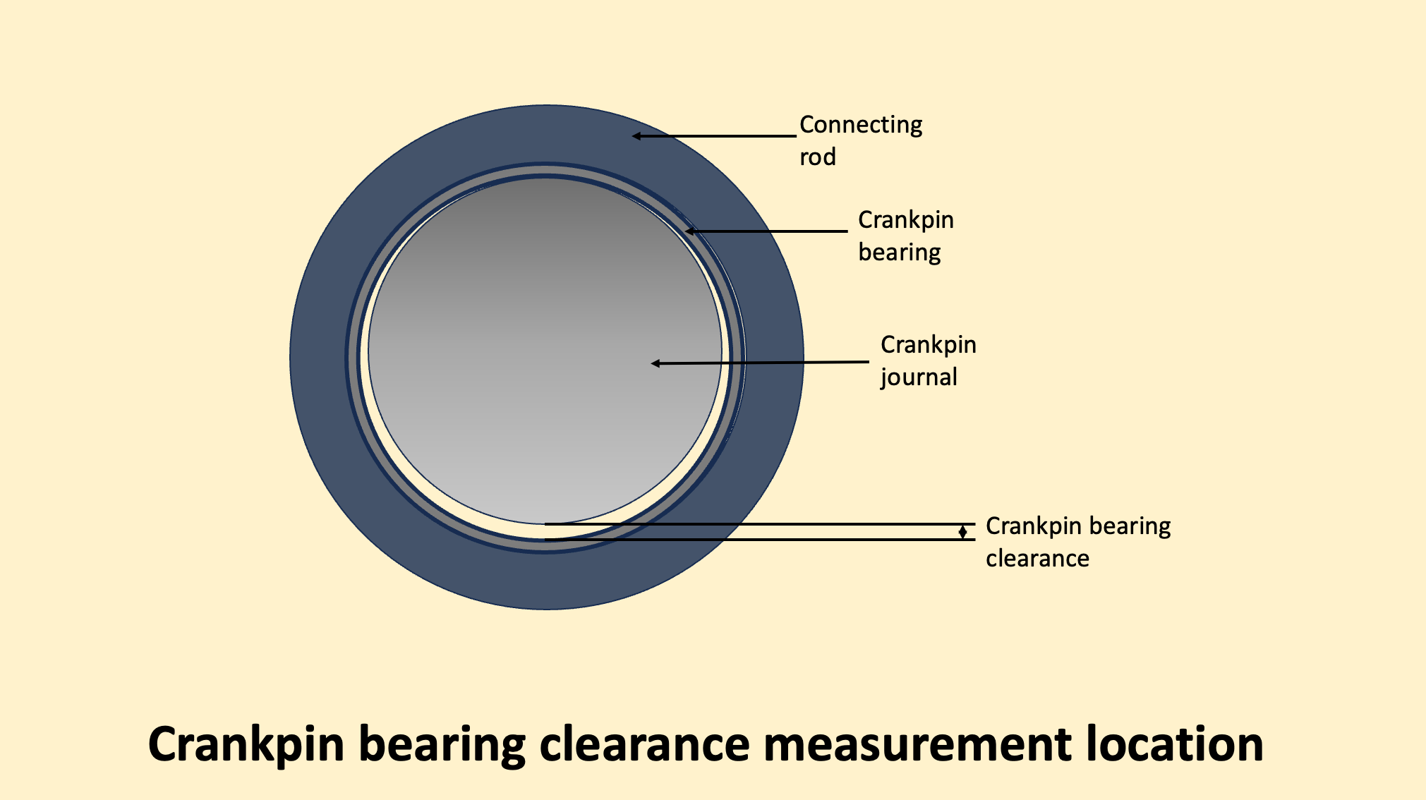
The crankpin bearing or bottom end bearing is placed between the crankpin and the connecting rod. It supports the load of the connecting rod, crosshead, and piston. When the engine is running, it transfers the gas forces from the connecting rod to the crankshaft.
The crankpin bearing clearance is always taken at the bottom side between the crankpin and the bearing. This is because the crankpin is always in contact with the top bearing half leaving clearance at the bottom.
Let us visualize how this happens during the compression and power strokes.
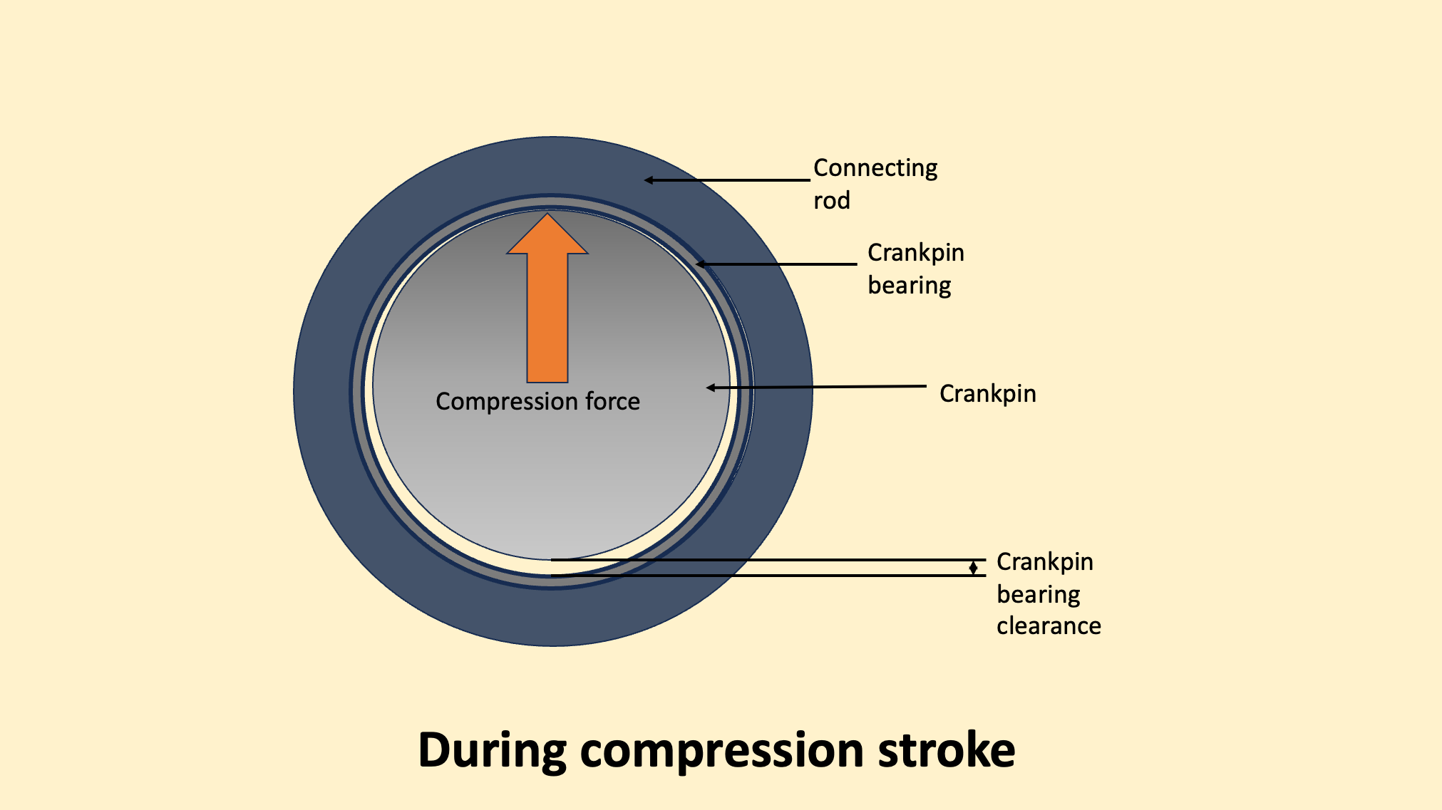
During the compression stroke, the crankshaft exerts the force on the piston. The force is transferred through the crankpin to the connecting rod and thus the contact is made at the top side of the bearing.
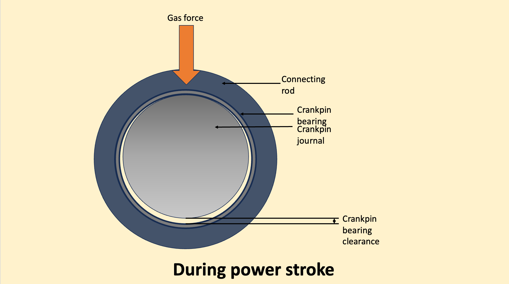
During the power stroke, the gas force is transferred to the crankpin by the connecting rod. This also results in contact between the crankpin and the bearing at the top region as the connecting rod pushes the crankpin down.
In either case, the contact is always maintained at the top end of the bearing. Thus, to take the clearance of the crankpin bearing, we need to insert the feeler gauge between the bottom of the crankpin and the bearing from both the forward and the aft side.
The position of the piston can be kept at any angle but generally, it is kept at BDC as it is the most convenient position to measure the crank pin bearing clearance. The typical value of bottom-end bearing clearance is around 0.4 mm.
Crosshead bearing clearance measurement
The crosshead bearing sits between the crosshead pin and the connecting rod. It transfers the forces from the piston rod to the connecting rod and vice versa.
To measure the crosshead bearing clearance, the piston position is 90 degrees before TDC on the exhaust side. This position allows us easy access to the crosshead. We insert the feeler gauge between the crosshead pin and the bearing cap, exactly next to the landing surface for the piston rod.

In some engines, there is a provision to insert the feeler gauge from the forward side of the bearing through a circular opening. Typical values for the crosshead bearings are around 0.45 mm.
Leave a Reply